20+ thermistor block diagram
This method of excluding the ADC from the component makes the. Functions are tested for.
Labview Block Diagram For An Ntc Thermistor Download Scientific Diagram
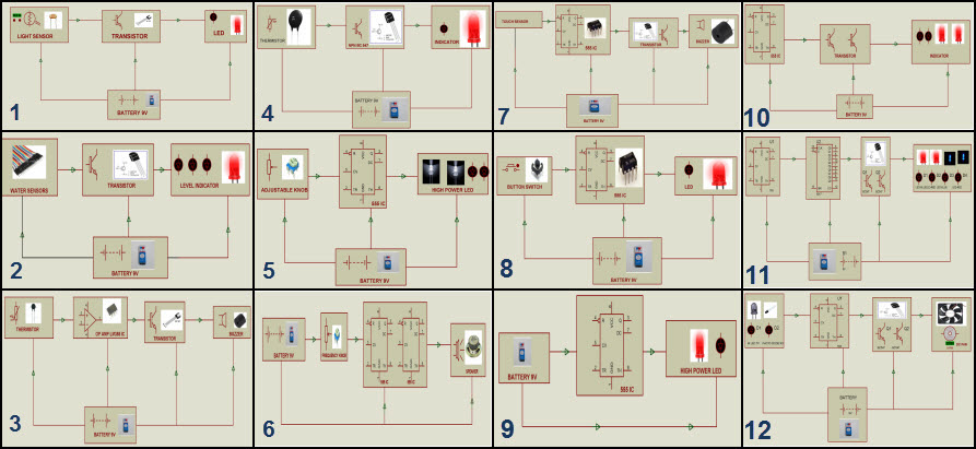
The block diagram of fire alarm circuit block diagram can be estimated based on the requirement and application of project.
. I believe it should look like this. Block diagram of temperature measurement system with thermistor is given in Figure 1. An example of a thermistor output curve can be.
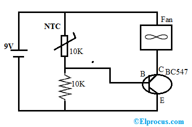
Insert the DAQ Assistant block onto. 20 30 40 50 Temperature oC Thermistor RT Curves For Varying Room Temperature Resistances Resistance thousands Figure 1. A simple potential divider arrangement using a thermistor is capable of sensing the temperature presence of fire and alerting us with a warning signal.
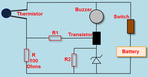
It follows a pre-defined curve which is provided by the thermistor manufacturer. Ntc thermistor temperature measurement interface circuit diagram 6 Fig. Fire Alarm Circuit Block Diagram Estimation.
Iconic Diagrams Pseudothermal Electric. Add all the other nodes shown in the diagram. The values are passed to the thermistor component through an API call.
Select Add output from the popup menu. Description This is a model of a linear thermis. The correct choice of resistors R2 and R3 will eliminate the average DC value of ΔV.
Library Iconic DiagramsThermalGenerators Use Domains. Resistance-Temperature response curves for. Thermistors change in resistance is non-linear.
There isnt one but you could use this one and edit it to create a new symbol for a thermistor. The NE555 timer IC works in Astable mode so it produces oscillating output for LED. It operates by the thermistor output voltage and controls the NE555 timer IC output.
Navigate to Express Input. 2 is an interface circuit. The return value of this API call is the temperature.
Open the Functions Palette. Finally select the Text tool and click on the Formula Node to enter the following. 11-13-2019 0738 AM.
Switch to the Block Diagram. Go to the Front Panel of your VI and delete the reading indicator. Contexts in source publication.
Heat Detector Circuit And Working Electronic Circuits
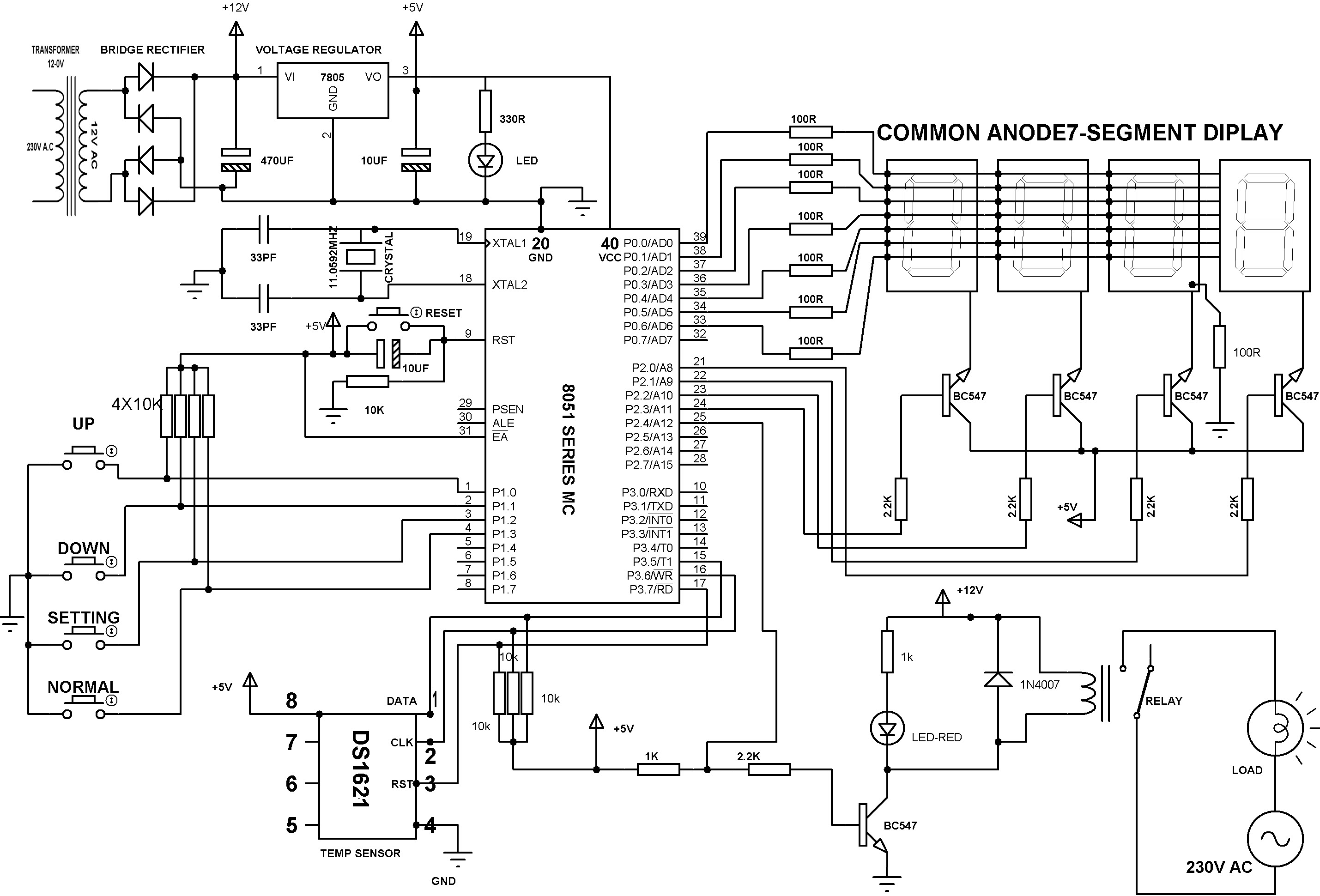
Precise Digital Temperature Controller Circuit Working And Its Applications

Schematic Diagram Of The Thermistor Probe Used For This Work Download Scientific Diagram
Steps To Build Simple Fire Alarm Circuit Using Thermistor
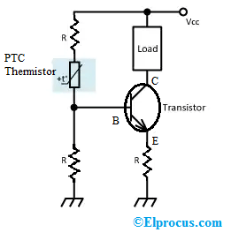
Ptc Thermistor Working Types Differences Its Applications

Tsi Schematic Diagram The Thermistor Body And Its Connections Are Download Scientific Diagram

Schematic Of The Thermistor Amplifier Circuit The First Opamp Circuit Download Scientific Diagram
Ntc Thermistor Working Types Characteristics Its Applications

Schematic Of Thermistor Structure Used Download Scientific Diagram

Tsi Schematic Diagram The Thermistor Body And Its Connections Are Download Scientific Diagram
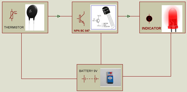
Steps To Build Simple Fire Alarm Circuit Using Thermistor
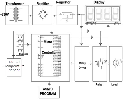
Precise Digital Temperature Controller Circuit Working And Its Applications

Block Diagram Of The Proposed Technique Download Scientific Diagram

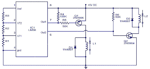
Schematic Diagram Of The Temperature Controller A Thermistor Serves As Download Scientific Diagram

Thermistor Temperature Sensor Circuit Sensing Alarm Circuits Circuit Circuit Diagram Electronic Schematics

Multi Ntc Thermistor Arduino Schematic Download High Resolution Scientific Diagram
Electronic Thermostat Circuit Diagram And Its Working